Introduction
This paper describes the design of a digital macro in a mixed-signal ASIC. The macro was designed using MyHDL, an open-source package that makes it possible to use Python as a hardware description language (HDL). The ASIC itself implements a multi-channel sensor interface. This is a high volume application in which reliability and cost are of prime importance.
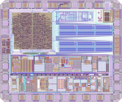
An image of the ASIC is shown below. The digital macro is the standard cell block located at the top left area of the die.
Using MyHDL for digital design is an innovative and unconventional approach, quite unlike today's mainstream design flows that are based on Verilog or VHDL. Nevertheless, several successful MyHDL-based FPGA projects have been reported recently. However, the author believes that the present paper represents the first report of the use of MyHDL for the design of a fully processed ASIC product.
The paper begins with an overview of the project organization, the digital macro functionality, and the MyHDL-based design flow. Then the advantages of MyHDL are discussed based on the experience from the present project.
Project organization
The term mixed-signal design means that both analog and digital blocks are combined on a single silicon die. Therefore, analog and digital design share a number of goals such as minimizing area and power consumption. However, the implementation techniques and the associated complexity of the two disciplines are fundamentally different. Analog design deals with the interactions between electronic devices such as transistors and capacitors, and with physical effects in silicon. Digital design, in contrast, is mostly concerned with logical behavior.
Successful mixed-signal design requires analog and digital design teams that are strong in their own discipline, but equally strong in understanding the needs of the other team and capable of efficiently interfacing with it. In this project, this challenge was met through a partnership between an analog design company, ICSense, and a digital design company, Easics. This partnership has delivered a number of successful mixed-signal design projects in the past and will be strengthened further in the future.
The architectural definition, RTL design, and RTL verification of the digital macro was carried out by the present author. He is a founder and director of Easics, and currently works as a consultant.
Digital macro functionality
The digital macro controls the operation of the chip, and performs a number of data processing functions. To give an idea of its complexity, an overview of its functional blocks is presented:
| Block | Functionality |
|---|---|
| SPI interface & registers | External controller based on an SPI interface, with corresponding registers. |
| OTP controller | Interface to an on-chip One Time Programmable (OTP) memory. Translates a number of high-level commands into the low-level serial memory interface. |
| Decimation filter | Digital decimation filter, applied to the data from the analog to digital convertor (ADC.) |
| Master controller | Controller of the overall schedule of the chip operations, depending on the operation mode. |
| Data transfer | Bit-serial transmitter of CRC-protected measurement data for all channels. Has a mode to send out OTP memory bits. Supports 4 data rates. |
| Analog control | Block with control signals for the on-chip analog circuitry. |
In addition, the macro contains a significant number of muxes and addional registers to enhance controllability and observability for testing purposes.
Digital design flow
The standard digital design was modified on a number of points to accomodate the use of MyHDL. The following is an overview of the design phases:
| Phase | Description | Tools | Deliverable |
|---|---|---|---|
| Architecture definition | Design partitioning; clock, reset and test strategy | Word processor, calculator | Architecture definition document |
| RTL design | RTL coding for all modules | Editor | MyHDL RTL code |
| RTL verification | Test bench coding and simulation | Editor, MyHDL simulator | Test suite in MyHDL |
| Conversion | Conversion to mainstream HDLs | MyHDL convertor, Verilog & VHDL simulators | VHDL RTL code, Test suite in Verilog & VHDL |
| Synthesis | RTL synthesis and test insertion | VHDL synthesis tool | Verilog gate level net list |
| Gate-level verification | Run test suite on gate level | Verilog gate level simulation | Sign-off to layout |
The text items in italics mark the differences when compared with a conventional design flow. In particular, the deliverable of the RTL design phase is MyHDL RTL code, which is is verified using the MyHDL simulator.
The main difference is an additional Conversion phase. In this phase, MyHDL code is automatically converted to both Verilog and VHDL. In this way, a MyHDL-based approach can be transparently integrated in a traditional design flow. In particular, a designer willing to experiment can test the waters by using MyHDL to design a single module, convert it, and proceed within his familiar and trusted design flow.
As can be expected, the conversion process is subject to a number of limitations. However, the convertible subset of MyHDL is much larger than the RTL synthesizable subset of Verilog and VHDL. In particular, it is also possible to convert relatively complex test benches. This was done in this project to convert the entire test suite to Verilog and VHDL.
MyHDL advantages
Introduction
Many designers are happy with Verilog and VHDL. Therefore, it makes little sense to propose a new approach like MyHDL unless it offers some clear and significant advantages. This section presents a discussion the advantages that were experienced in the present project.
In addition to the fact that MyHDL is an open source product, available at no cost, it offers a number of technical advantages. These will be described in the following subsections.
MyHDL concepts
Conceptually, MyHDL is not a new language. Rather, it is a way to use Python as a hardware description language.
In its basic conception, MyHDL consists of a Python package and a Python usage model. The package contains a number of objects that are suited for hardware design purposes, such as a VHDL-like signal class, and a class for bit-oriented operations. Also included are a class used to simulate a design, and functions to convert a design to Verilog and VHDL. The usage model proposes the application of Python generators to model blocks of concurrent hardware behavior. Generators used in this way are similar to Verilog always blocks and VHDL processes.
The Python foundation of MyHDL is a fundamental design decision. It implies that the MyHDL designer directly benefits from all progress made on the Python language itself. Most importantly, the designer can directly reuse all resources available in the vast standard library and in third party libraries.
Designing hardware with a dynamic language
Verilog and VHDL are statically typed languages. The software equivalents are languages like C++, Ada and Java. However, in the software development world another family of languages is very popular: dynamically typed languages. Well known examples include Perl, Python, Ruby and Tcl. Many engineers like to use these types of languages because of their flexibility and power. Actually, these languages also play an important support role in many hardware design flows.
Use of dynamic languages is ideal during the creative phase at the front end of the design process, when expressive power and ease of experimentation are more important than raw runtime performance. The MyHDL value proposition is to make these features available in a hardware description language itself.
The MyHDL type system
In traditional HDLs, the most popular types for describing integer arithmetic are signed and unsigned types, modeled after similar types in mainstream programming languages. According to the present author, this situation is far from ideal. These types force HDL designers to deal explictitly with bit representation issues. The result is code with a lot of explicit type casts, sign extensions and resizings, even for simple integer operations.
MyHDL has a better solution, as it improves upon a concept borrowed from VHDL: the integer subtype, which is an integer constrained by a lower and upper bound. Unlike VHDL, MyHDL does not specify any artificial limits on the bounds. As a result, the MyHDL designer can describe integer arithmetic very naturally, regardless of the underlying bit widths. All low level representational issues are handled automatically by the convertor to Verilog and VHDL.
Conversion to both Verilog and VHDL
The reality of contemporary HDL design is that Verilog and VHDL are almost equally popular. As a result, many design flows need provisions for dealing with both languages in a single project. In a number of cases, MyHDL provides an innovative and elegant solution, because it can convert designs and test benches to equivalent Verilog and VHDL, subject to reasonable restrictions.
The MyHDL dual conversion capability proved very useful in the present project. For example, the sign-off language for RTL synthesis was VHDL, but the sign-off language for layout was Verilog. Thus, having an equivalent VHDL and Verilog test suite for RTL and gate level simulation was very handy. Moreover, a third-party memory model was more mature in Verilog than in VHDL. Therefore, the Verilog test suite provided an additional level of confidence. Furthermore, the analog design partner had a mixed-signal simulation capability based on Verilog. This could be tested out early on with an RTL module converted to Verilog.
Test-driven hardware development
It is often claimed that the bottleneck in today's HDL design flows is not so much the design implementation itself, but the verification task. As a result, a number of innovative verification solutions have been developed, such as assertion-based verification and constrained random simulation.
However, remarkably, the verification-related innovations that are happening in the software development world are seemingly being ignored by the hardware design community. The author considers this to be unjustifiable, because he believes that HDL-based design can be regarded as a special kind of software development.
A very powerful modern software verification technique is test-driven development (TDD). (In this context, the word "test" refers to functional verification, not manufacturing test.) One aspect of this technique is a unit test framework, which is a software platform that facilitates the development of tests for small pieces of behavior. The MyHDL designer has a choice of several of the unit test frameworks available for Python. However, the most important aspect of TDD is as a methodology. The idea is to develop the test before the implementation. In fact, the implementation is said to be driven by a set of existing tests.
TDD was successfully used in the present project, as illustrated by the following example. The project contained a decimation filter whose expected behavior could be easily specified and coded at a high level in Python. This specification was used to develop a number of unit tests, for special and corner cases and for a large number of random data sets. This test suite was then used to drive the RTL development for the module. At the start, all tests failed, but as the RTL design progressed, incrementally more of the tests began to work. When all of the tests worked, the design work was finished.
It is interesting to highlight the advantages of TDD over a traditional work flow, when tests are written only after the implementation:
- It is very motivating for a designer to see increasingly more tests work as his implementation progresses.
- The completeness of an implementation is signalled automatically.
- Writing the test first guarantees that the designer's mind is not yet cluttered with implementation details. This makes it easier to develop complete tests covering all features including corner cases.
- All tests fail initially. This guarantees that the tests can differentiate between a good and a bad design, ensuring a high test suite quality.
- The test suite stays in place as a regression test. Subsequent incremental design changes can thus be made with confidence.
This list of advantages makes it all the more remarkable that TDD is receiving virtually no attention in the hardware design community. The most important, albeit indirect, MyHDL innovation may therefore be that it puts TDD into the hands of hardware designers. The methodology could be called test-driven hardware development (TDHD). This author believes that this novel idea has a very promising future.
Conclusion
The design of a digital macro with MyHDL is described. This project validates the suitability of MyHDL for industrial projects, for which reliability and efficiency are of prime importance. Moreover, a MyHDL-based design flow is shown to offer a number of significant advantages over traditional approaches.
Acknowledgments
The author wishes to thank Bram De Muer, Wim Claes and Nico Boom from ICsense, and also Ramses Valvekens and Jan Zegers from Easics, for the stimulating cooperation on an interesting project, and for providing the opportunity to demonstrate the capabilities of MyHDL-based design.